The 1902 is a versatile modular unit designed to work with modern computer-controlled data acquisition systems. Developed for a broad range of applications, the 1902 accepts biological and instrumentation signals from a wide variety of sources.
It is available in single or multi channel configurations. Communication with the computer is achieved through a serial line, allowing multiple sets of units to be controlled simultaneously.
EMG, EEG, ECG, ERG
Evoked response
TMS studies
Skin Conductance
Tremor Measurement
Auditory Brainstem
...and many more life science and engineering research applications
A major advantage of programmable amplifiers is the degree of interaction between the signal conditioner and the application software recording the data. The 1902 is directly controlled through the CED data acquisition and analysis programs Spike2 and Signal, or through a stand-alone control application.
Trigger input converter from high-level pulses or switch closures to 5V TTL
Overload indicators with software readback
EMG filter with full wave rectifier and programmable post-filter gain
16-bit ADC for digitisation of transducer and other low-bandwidth signals and transmission of results down the serial line
Programmable gain with readback
Digital filters generated according to user-entered filter cut off values
Optional input clamping
Selectable mains notch filter
AC/DC coupling
Dynamically controlled 12-bit offset

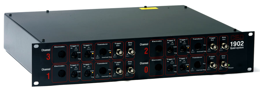
1902 control panel
The 1902 is designed to a specification worked out in conjunction with major UK physiological laboratories for an isolated amplifier to comply with EN 60601-1. It provides a low noise differential electrode input developed specifically for EEG, EMG, ECG and evoked potential applications.
IMPORTANT NOTE: The 1902 is research equipment and is not sold as a medical device within the meaning of the European Medical Devices Directive.
The transducer input port is suitable for use with a wide range of bridge and other transducers. It will accept single-ended and differential inputs and provides 5 volt and 12 volt outputs to supply the excitation voltages required by many transducers. Applications include: isometric force, strain gauges, temperature, pressure, acceleration, displacement and goniometers.
The 1902 is available in a transducer-only form with no isolated electrode input.

|
|
|
| Bandwidth | DC to 10 kHz (-3dB) in DC mode 0.16 Hz to 10 kHz in AC mode |
| Gain accuracy | ±2% |
|
|
|
| Filter response | Bessel or Butterworth |
| Filter slope (low- and high-pass) | 2nd or 3rd order (12 or 18 dB/octave) |
| Low pass filter corner frequency | 1 Hz - 10 kHz cont. variable |
| High pass filter corner frequency | 0.01 Hz - 1 kHz cont. variable |
| Filter latency | 0.35 ms (approx.) |
| Rectification | User-selectable |
|
|
|
| Mains notch cut (50 Hz or 60 Hz) | 50 dB (typical) |
| Overload indicator | 2 yellow LEDs (1 for each polarity) indicate when input is overrange |
|
|
|
|
|
|
|
|
|
| Important note: The CED 1902 is sold as a research instrument and not as a medical device within the meaning of the EC Medical Device Directive. | |
|
|
|
| Input impedance | 1 GOhm |
| Input bias current at 25 °C | 50 nA |
| Common mode rejection (at x100 gain) | 80 dB at 50 Hz |
| Bandwidth | DC - 10 kHz |
| Gains | x1 to x100,000 |
| Gain step sequence | 1, 3, 10 |
| Gain accuracy | ±2% |
| Noise 1 Hz to 10 KHz (at x100 gain) | 1 microV r.m.s. |
|
|
|
| 1902 chassis mechanical dimensions | Width 240 x height 46 x depth 240 mm |
| 1902 weight (approx.) | 2.5 Kg |
| Power input | 100 - 240V AC external power supply (PSU can supply up to four 1902s) |
| PSU weight | 750g |
|
|
||
| Front end type | Low noise EEG | ECG |
| Input impedance |
|
|
| Input bias current at 25°C |
|
|
| Noise referred to input, 1 Hz - 10 kHz |
|
|
| Common-mode rejection at 50 Hz |
|
|
| Common-mode voltage range |
|
|
| Input offset voltage, initial adjusted |
|
|
| Gain ranges (including 1902 system board) |
|
|
| Gain step sequence |
|
|
| Gain accuracy |
|
|
| Bandwidth, all gains |
|
|
| Isolation voltage, continuous |
|
|
| Isolation voltage, peak for 5 sec |
|
|
| Input-output leakage at 240V, 50 Hz |
|
|
| Input clamp option |
|
|
| Lead configurations |
|
|
| Calibrator |
|
|
|
|
|
| Input impedance | 100 kOhms |
| Voltage range | ±15V |
| Trigger polarity | Selectable |
| Trigger level | +1.25 (approx.) |
| Trigger hysteresis | +0.5V (approx.) |
| Output pulse | TTL negative-going |
| Output pulse length | 3 microSec |
| Trigger output drive capability | 0.9 mA maximum |
Items marked with* are investigational devices and for research use only. CAUTION - Investigational Device. Limited by Federal (or United States) law to investigational use.